[Get 18+] Motor Control Slip Ring Motor Starter Wiring Diagram
Download Images Library Photos and Pictures. Manual Speed Controllers For Wound Rotor Induction Motors Medium Voltage Soft Starter For Heavy Duty Motor Control Eep Wound Rotor Motors And Manual Speed Control Electric Equipment Wound Rotor Motors And Manual Speed Control
Check more diagrams here. Because of various advantages like low initial current high starting torque and improved power factor it is used in applications that require high torque cranes and elevators.
. Know How To Control The Speed Of Slip Ring Motors Bright Hub Engineering Electrical Engineering What Is The Starting Of Slip Ring Induction Motors Three Phase Drum Starter
Https Encrypted Tbn0 Gstatic Com Images Q Tbn And9gcranvypydjpejzxthljxjeiktypinxim2csse2kfducwf Atcu0 Usqp Cau
Https Encrypted Tbn0 Gstatic Com Images Q Tbn And9gcranvypydjpejzxthljxjeiktypinxim2csse2kfducwf Atcu0 Usqp Cau But how does external resistance aid in better starting characteristics.
. Also know about the qualities of slip ring induction motors. Three phase slip ring rotor starter control power diagrams. Basic wiring for motor control technical data.
Schematic diagram of magnastart system connection terminal and internal wiring principle diagram electrical machines basic vocational knowledge 5 asynchronous motors 4 circuit engineering 1 starting connections electrical machines basic vocational knowledge 5 asynchronous motors 4 circuit engineering 1 starting. Two speeds one direction. In the induction motors used in lift and hoists you will see a type of rotor called.
The following diagram depicts 3 phase non reversing motor control with 24 vdc control voltage and manual operation. Posted on 1 december 2020 by admin. Induction motors have been ruling the industrial world for many decades.
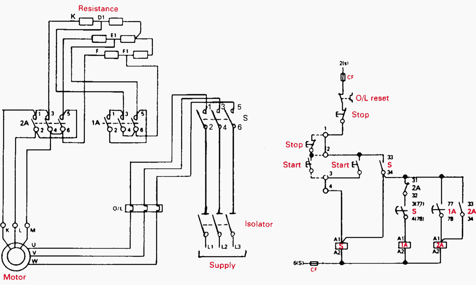
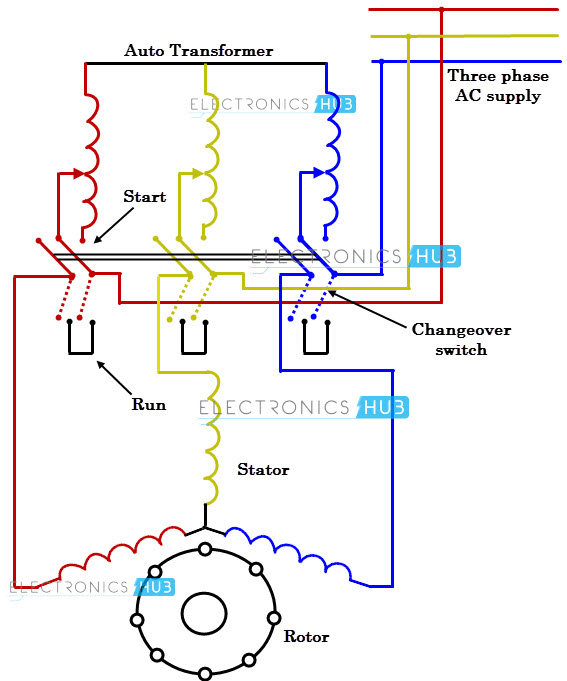
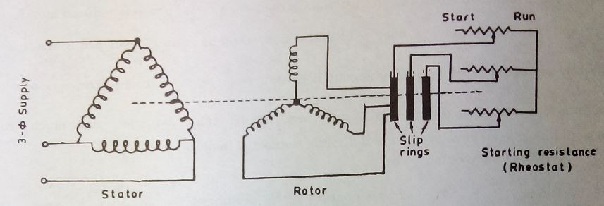
Slip ring motor resistance connection diagram. Three phase slip ring rotor starter control diagram control diagram. The rotor windings consist of more number of windings higher induced voltage and less current compared to.
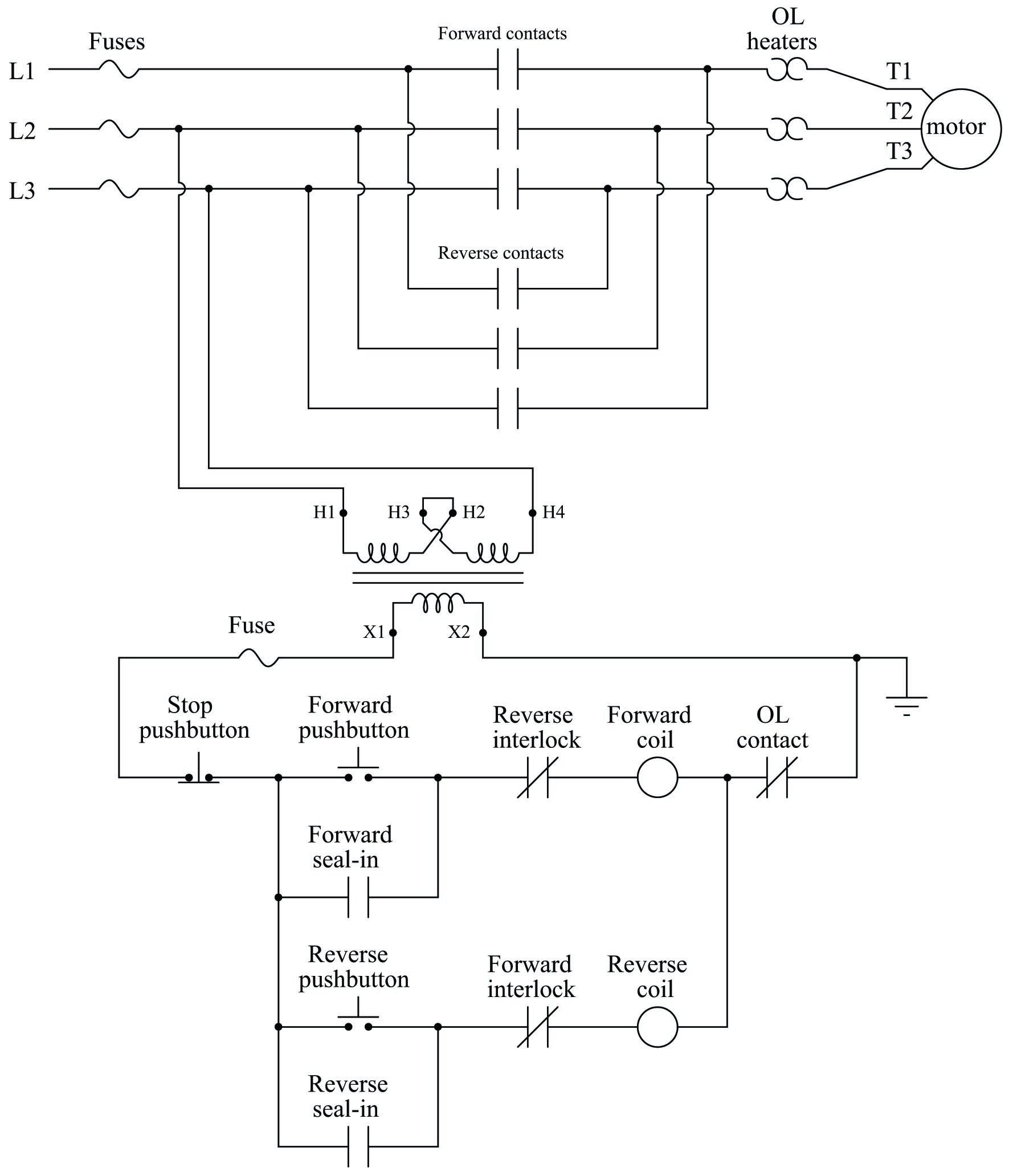
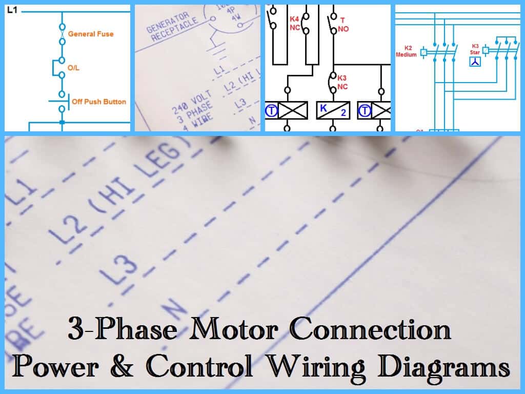
On off three phase motor connection power control schematic and wiring diagrams. Wiring diagrams show the connections to the controller. Three phase motor control installation wiring diagrams electrical technology.
Control 3 phase motor from more than two buttons power control diagrams. They show the relative location of the components. The start and stop circuits can also be controlled using plc inputs and outputs.
Single phase motor starter wiring diagram pdf a novice s overview of circuit diagrams. The above wiring diagram assumes your magnetic starter has a 240v coil. Three phase motor connection reverse and forward power and control wiring diagrams.
Slip ring induction motor is one of the types of 3 phase induction motor and is a wound rotor motor type. Read here to know about the starting arrangement and the role played by the external resistances in obtaining better starting characteristics. We will use a contactor an auxiliary contact block an overload relay a normally open start pushbutton a normally closed stop pushbutton and a power supply with a fuse.
Merely ignore the control wiring in red 3ph starter1ph motor line voltage control three phase 3ph motor starter controlling a single phase motor rev 08 aug 2006 some 3 phase magnetic. A very first look at a circuit diagram could be complicated yet if you can read a metro map you can review schematics. Wiring diagrams sometimes called main or construction diagrams show the actual connection points for the wires to the components and terminals of the controller.
If you have a 120v coil instead of running a line from coil overload l2 you must run coil overload neutral. A slip ring induction motor can be started with external resistance added in its rotor circuit. They can be used as a guide when wiring the controller.

 3 Phase Slip Ring Induction Motor View 3 Phase Slip Ring Induction Motor Ps Product Details From Monarch Controls On Alibaba Com
 Schematic Diagram Of The Drive With The Slip Ring Induction Motor Download Scientific Diagram
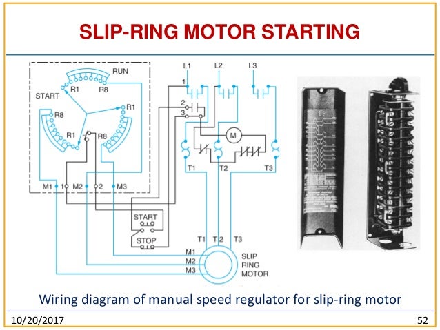
 Kg 5951 Speed Control Of Slip Ring Induction Motors Part Ii Wiring Diagram
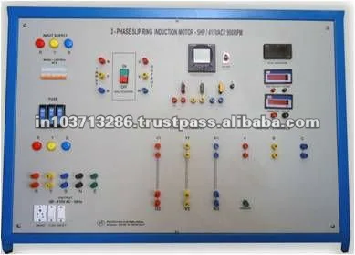
 Three Phase Ac Slip Ring Induction Motor With Control Panel Power 5 Hp Voltage 415 V Rs 26000 Piece Id 12678439148
Develop Power And Control Diagram For Secondary Frequency Acceleration Starter Of Slip Ring Induction Motor Questions Answers
 On Off Electric Motor Control Circuits Discrete Control System Elements Automation Textbook
Https Encrypted Tbn0 Gstatic Com Images Q Tbn And9gcqailuls Tsd2uptupzp0pyqofdmdpcbhy1tm9wdmbeibnn5ips Usqp Cau
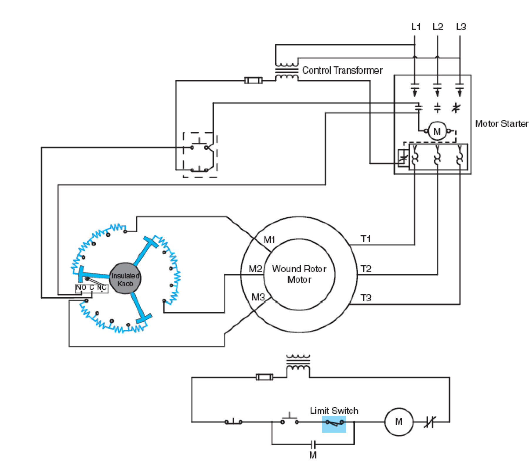 Refer To The Basic Control Schematic In Figure 34 4 The Limit Switch Is Shown As A Normally Open B Normally Closed C Normally Open Held Closed D Normally Closed Held Open Fig
 Starting Methods Of Three Phase Induction Motors Electricaleasy Com
 Contactor As An Important Part Of The Motor Control Gear Eep

 Rotor Resistance An Overview Sciencedirect Topics

 What Is Motor Starter
 Three Phase Motor Power Control Wiring Diagrams
How Would The Windings Be Shorted When A Slip Ring Induction Motor Is Running Quora
 Motor Control Modernization Improves Pump Performance Waterworld

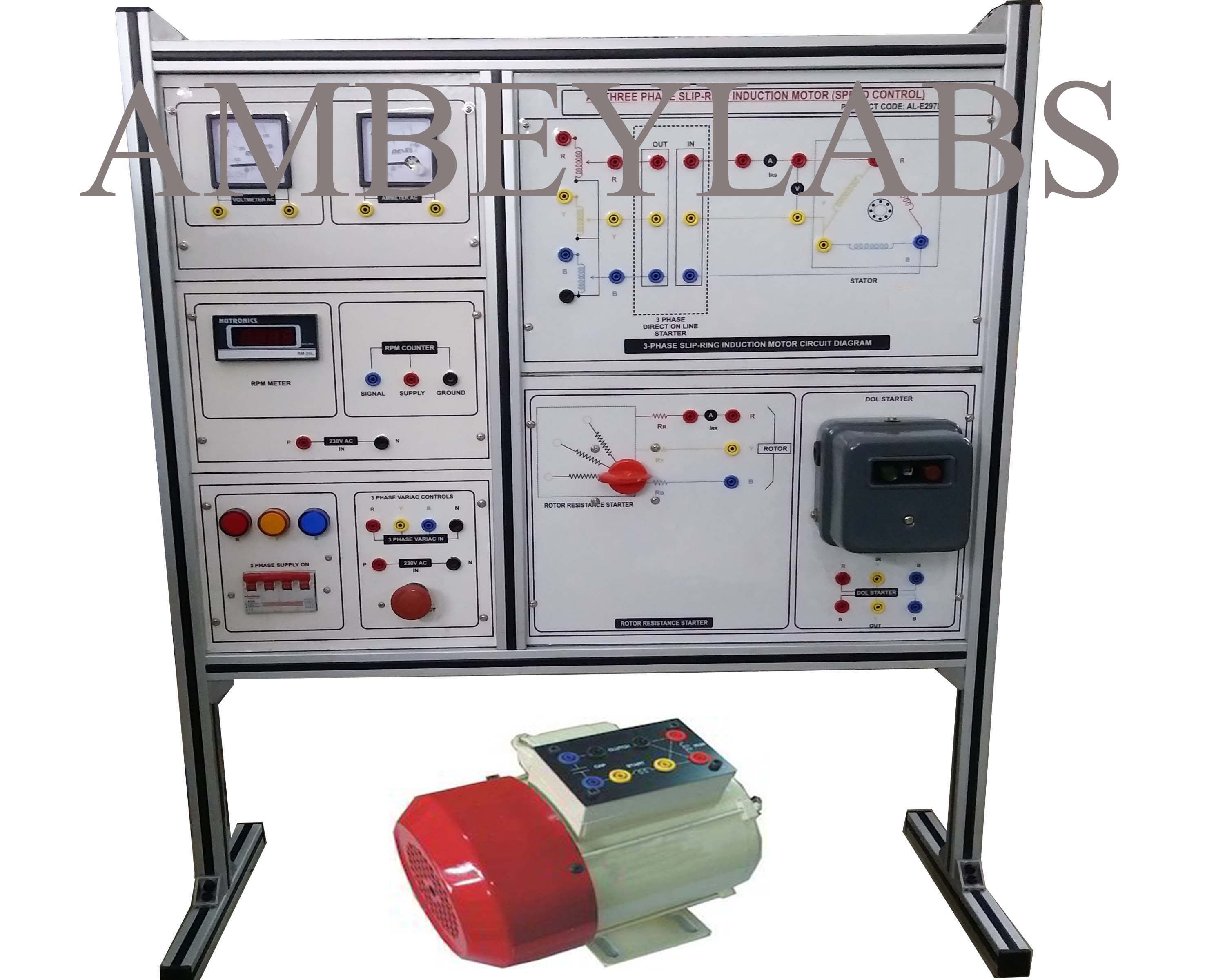 Product Id Al E297c Three Phase Ac Slip Ring Induction Motor Speed Control 429
 Contactor As An Important Part Of The Motor Control Gear Eep

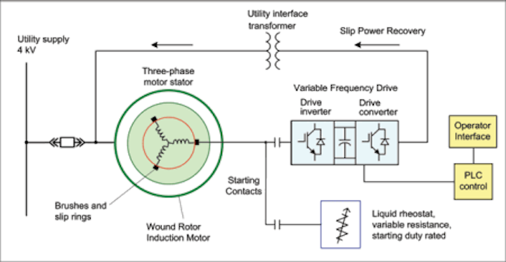
 Supplemental Material For Electrical Drive System
 1000 Hp Slip Ring Type Induction Motor And Its Starter Lrs Liquid Re
 Starting Methods Of Induction Motor Your Electrical Guide


Komentar
Posting Komentar